EMF and Terminal Voltage: Powering Your Understanding
Dive into the world of electromotive force and terminal voltage. Our comprehensive guide and video tutorials break down complex concepts, making it easy to grasp these essential electrical principles.

Now Playing:Emf and terminal voltage – Example 0a
Intros
  1. Introduction to EMF and Terminal Voltage:
  2. Introduction to EMF and Terminal Voltage:
    How do we make our physics circuits more realistic?
  3. Introduction to EMF and Terminal Voltage:
    What is internal resistance?
Examples
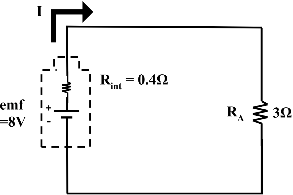
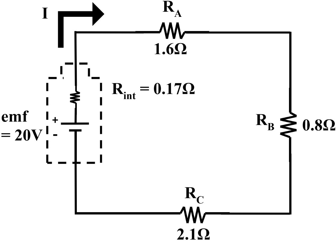
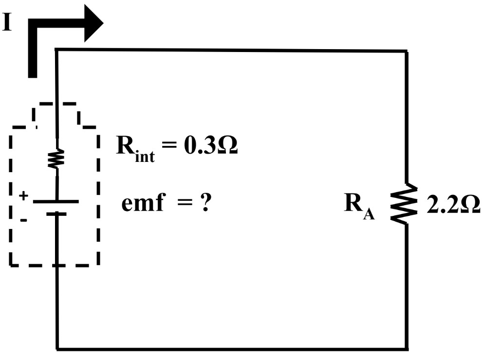
  1. Calculating Internal Resistance and Terminal Voltage using Two Methods

    EMF Terminal Voltage
    1. Using the traditional terminal voltage formula method:
      1. Calculate the voltage used by the internal resistor of the battery.
      2. Calculate the terminal voltage.

    2. Using the voltage divider method:
      1. Calculate the voltage used by the internal resistor of the battery.
      2. Calculate the terminal voltage.

Voltage
Notes

In this lesson, we will learn:

  • How to compare and contrast the circuits we’ve been drawing so far (an ideal circuit) with a more realistic circuit (containing an EMF as well as internal resistance).
  • What is EMF (Electromotive Force)? And what is terminal voltage?
  • How to solve for terminal voltage and EMF using 2 methods:
    • The traditional formulas for Ohm’s Law (V=IRV=IR ) and terminal voltage formula (Vterm=ϵIrV_{term} = \epsilon- Ir )
    • Conceptual understanding and voltage divider formula ( Vx=VtotalRxRtotal V_{x} = V_{total} \, \cdot \, \frac{R_{x} } {R_{total} } )

Notes:

  • To represent a more realistic electric circuit, a battery actually contains internal resistance—in other words, the battery itself uses up some of the voltage that it provides to the whole circuit.
    • Internal resistance is unavoidable because any material has some resistance
    • Metals have a very low (but not zero) resistance and are good conductors for electricity; the greater the resistance of a material, the worse its conductivity

  • EMF stands for Electromotive Force. It is a device that transforms one type of energy into electrical energy. (i.e. An alkaline battery undergoes redox reactions whereby chemical energy is transformed into electrical energy to power the circuit).

  • A battery is considered a source of electromotive force. A battery is actually composed of an EMF (ϵ \epsilon) and an internal resistor (RintR_{int} or rr ) connected in series.

  • Terminal Voltage (VtermV_{term}) is the voltage (potential difference) measured between the terminals (positive and negative terminals) of a battery.
    • When no current is flowing through the circuit: emf = terminal voltage
    • When there is current flowing through the circuit: emf > terminal voltage

  • The general formula for the Terminal Voltage is given as:
    • Vterm=ϵIrV_{term} = \epsilon- Ir

  • Where:
    • VtermV_{term} is the voltage between the terminals of the battery (in volts, V)
    • ϵ \epsilon is the EMF of the battery; total/maximum voltage (in volts, V)
    • II is the total current flowing through the circuit (in amperes, A)
    • rr is the internal resistance within the battery (in Ohms; Ω \Omega )
    • IrIr is actually the voltage drop across the internal resistor (V=IRV = IR), thus the formula can be adjusted: Vterm=ϵVr V_{term} = \epsilon - V_{r}

  • Furthermore, the terminal voltage represents the amount of electric potential energy (voltage) that is available to the circuit outside of (external to) the battery itself. Thus:
    • Vterm=Vusedup=Vexternal V_{term} = V_{used \, up} = V_{external}
    • And the Vtotal V_{total} or ϵ=Vinternalresistor=Vexternalresistor(s) \epsilon = V_{internal \, resistor} = V_{external \, resistor(s)}

  • To modify the voltage divider general formula to be used with EMF and terminal voltage questions, we can solve for the total external voltage drop:
    • Vterm=Vext=ϵRextRtotal V_{term} = V_{ext} = \epsilon \, \cdot \, \frac{R_{ext} } {R_{total} }
Concept

Introduction to EMF and Terminal Voltage

Welcome to our exploration of EMF (electromotive force) and terminal voltage! These fundamental concepts are crucial for understanding how electrical circuits work. EMF refers to the energy per unit charge provided by a source, while terminal voltage is the actual potential difference across a device's terminals. Our introduction video serves as an excellent starting point to grasp these ideas. It visually demonstrates how EMF and terminal voltage relate to each other and their roles in circuit analysis. As we delve deeper, you'll discover how these concepts apply to real-world scenarios, from simple battery-operated devices to complex electrical systems. The video breaks down these potentially challenging topics into easily digestible segments, making it an invaluable resource for both beginners and those looking to refresh their knowledge. So, let's dive in and unravel the mysteries of EMF and terminal voltage together!

Example

Understanding the concepts of Electromotive Force (EMF) and terminal voltage is crucial for making physics circuits more realistic. This guide will walk you through the steps to achieve a more accurate representation of these concepts in your circuits.

Step 1: Understanding EMF

Electromotive Force (EMF) is the energy provided by a source, such as a battery or generator, per unit charge. It is the driving force that pushes electrons through a circuit. EMF is measured in volts (V) and is often denoted by the symbol ε. To make your circuits more realistic, it is essential to understand that EMF is not the same as the terminal voltage, especially when a current is flowing through the circuit.

Step 2: Understanding Terminal Voltage

Terminal voltage is the voltage output of a device measured across its terminals. When a current flows through a circuit, the terminal voltage is usually less than the EMF due to the internal resistance of the source. This internal resistance causes a voltage drop within the source, which must be accounted for to make your circuits more realistic. The terminal voltage can be calculated using the formula: V_terminal = EMF - (I * r), where I is the current and r is the internal resistance.

Step 3: Incorporating Internal Resistance

To make your circuits more realistic, include the internal resistance of the power source in your calculations and circuit diagrams. Internal resistance is an inherent property of all real-world power sources and affects the terminal voltage. By incorporating this resistance, you can better predict the behavior of your circuit under different loads.

Step 4: Measuring EMF and Terminal Voltage

Use a voltmeter to measure the terminal voltage across the terminals of the power source. To measure the EMF, you need to measure the voltage when no current is flowing (open-circuit condition). This can be done by disconnecting the load and measuring the voltage across the terminals. Understanding the difference between these two measurements will help you design more accurate and realistic circuits.

Step 5: Analyzing Circuit Behavior

Analyze how the internal resistance and the load resistance affect the terminal voltage and overall circuit performance. Use Ohm's Law and Kirchhoff's Voltage Law to calculate the expected voltage drops and currents in the circuit. This analysis will help you understand the impact of internal resistance on the circuit's behavior and make necessary adjustments to improve accuracy.

Step 6: Simulating Real-World Conditions

Use circuit simulation software to model your circuits with realistic parameters, including internal resistance and varying loads. Simulation tools can help you visualize the effects of different components and conditions on your circuit's performance. By simulating real-world conditions, you can identify potential issues and optimize your circuit design for better accuracy.

Step 7: Practical Testing and Validation

Build and test your circuit in a real-world setting to validate your theoretical calculations and simulations. Measure the terminal voltage and current under different load conditions and compare them with your predictions. This practical testing will help you identify any discrepancies and refine your circuit design for improved realism.

Step 8: Continuous Learning and Improvement

Stay updated with the latest research and advancements in circuit design and EMF concepts. Continuously improve your understanding and application of these principles to make your circuits more realistic. Engage with the physics and engineering community to share knowledge and learn from others' experiences.

FAQs

Here are some frequently asked questions about EMF and terminal voltage:

1. What is the difference between EMF and terminal voltage?

EMF (electromotive force) is the maximum potential difference a source can provide under ideal conditions, while terminal voltage is the actual voltage measured across the terminals when current is flowing. Terminal voltage is typically lower than EMF due to internal resistance.

2. How is terminal voltage calculated?

Terminal voltage is calculated using the formula: V = E - Ir, where V is terminal voltage, E is EMF, I is current, and r is internal resistance. This equation shows how terminal voltage decreases as current increases due to voltage drop across the internal resistance.

3. Why is EMF usually higher than terminal voltage?

EMF is higher than terminal voltage because of the voltage drop caused by internal resistance. When current flows through a power source, some voltage is lost overcoming this internal resistance, resulting in a lower terminal voltage compared to the EMF.

4. How do you measure the EMF of a battery?

To measure EMF, use a high-impedance voltmeter across the battery terminals when no current is flowing (open circuit). This minimizes current draw and provides a reading close to the true EMF. For more precise measurements, a potentiometer method can be used.

5. What is the importance of understanding terminal voltage in practical applications?

Understanding terminal voltage is crucial in various applications, including battery management in electronic devices, automotive electrical systems, and power supply design. It helps in predicting actual voltage available under load, optimizing circuit performance, and diagnosing issues in electrical systems.

Prerequisites

Understanding EMF (electromotive force) and terminal voltage is a crucial concept in electrical engineering and physics. While there are no specific prerequisite topics listed for this subject, it's important to recognize that a strong foundation in basic electrical principles is essential for grasping these concepts fully. Having a solid understanding of fundamental electrical concepts will greatly enhance your ability to comprehend and apply the principles of EMF and terminal voltage.

EMF and terminal voltage are interconnected concepts that play a vital role in electrical circuits and power systems. EMF refers to the potential difference generated by a source of electrical energy, such as a battery or generator, while terminal voltage is the actual voltage measured across the terminals of a power source when it's connected to a circuit. These concepts are fundamental to understanding how electrical energy is produced, transferred, and utilized in various applications.

To fully appreciate the intricacies of EMF and terminal voltage, it's beneficial to have a good grasp of basic electrical principles. This includes understanding concepts such as voltage, current, and resistance, as well as Ohm's law and Kirchhoff's laws. Familiarity with these foundational topics will provide you with the necessary context to explore EMF and terminal voltage in greater depth.

Additionally, knowledge of circuit analysis techniques and the behavior of different circuit components can greatly enhance your understanding of EMF and terminal voltage. Being able to analyze simple and complex circuits will allow you to see how EMF and terminal voltage interact with other elements in a circuit, such as resistors, capacitors, and inductors.

Furthermore, a basic understanding of electromagnetic theory can provide valuable insights into the underlying principles of EMF generation. This includes concepts such as magnetic fields, electromagnetic induction, and Faraday's law. These topics help explain how EMF is produced in various electrical devices and systems.

While specific prerequisite topics are not listed for EMF and terminal voltage, it's clear that a strong foundation in electrical fundamentals is crucial. By building your knowledge in these areas, you'll be better equipped to tackle the complexities of EMF and terminal voltage, as well as their applications in real-world electrical systems.

As you delve into the study of EMF and terminal voltage, remember that these concepts are not isolated but are part of a broader understanding of electrical phenomena. They play a significant role in the design and operation of electrical devices, power distribution systems, and renewable energy technologies. By mastering these concepts, you'll gain valuable insights into how electrical energy is harnessed and utilized in our modern world.

In conclusion, while there may not be a specific list of prerequisites for studying EMF and terminal voltage, a solid grounding in electrical fundamentals will serve as an excellent foundation. As you progress in your studies, you'll find that your understanding of these core concepts will continually deepen and expand, allowing you to tackle more advanced topics in electrical engineering and physics with confidence.