Electric Generators and Counter EMF: Core Concepts
Dive into the world of electric generators and counter EMF. Understand AC/DC differences, generator structures, and EMF calculations. Perfect for students seeking in-depth knowledge of electromagnetism.

Now Playing:Electric generators and counter emf back emf – Example 0a
Intros
  1. Introduction to motors and electric generators
  2. ac generator
Examples
  1. A motor is connected to a 12V dc supply and draws 5.0A when it first starts up. What will be the back emf when the motor is operating at full speed and drawing 1.2 A?
    1. 7.0 A
    2. 7.8 A
    3. 9.1 A
    4. 10.8 V
    Induced EMF and Lenz’s law
    Notes

    In this lesson, we will learn:

    • Alternating Current (ac) VS. Direct Current (dc)
    • Motor VS. Electric Generator
    • ac Generator Principles
    • dc Generator Principles
    • Counter emf (Back emf)

    Notes:


    Alternating Current (ac) VS. Direct Current (dc)


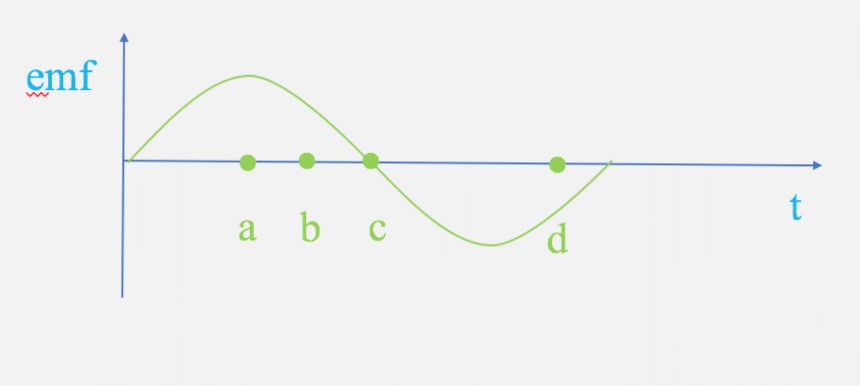
    ac: A current that changes its sense with time is called the alternating current. (Example; ac generator)
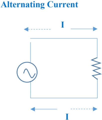
    Electric Generator and Counter EMF


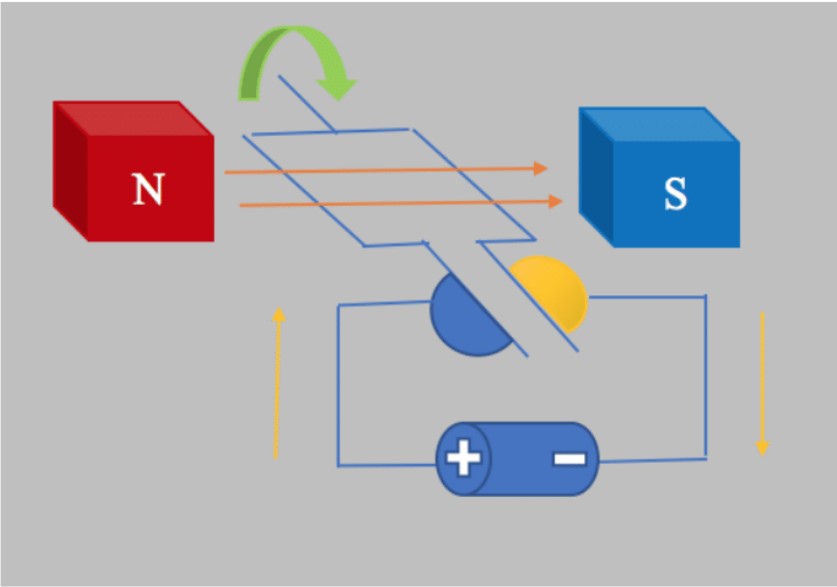
    dc: A current that flows only in one direction is called the direct current. (Example; dc Motor)
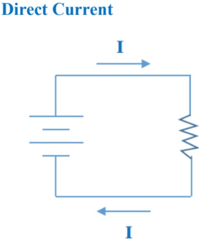
    Electric Generator and Counter EMF


    Motor VS. Electric Generator

    Motor: transfers electrical energy into mechanical energy.


    Electric Generator and Counter EMF


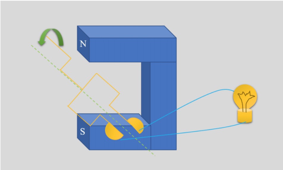
    Electric generator or Dynamo:transforms mechanical energy into electrical energy.


    Electric Generator and Counter EMF


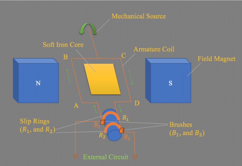
    AC generator: A generator that consists of many loops of wire wound around an armature that rotates in a magnetic field. The axle connected to the armature rotates by some mechanical means such as; falling water, steam turbine, etc. As the coil rotates, an emf is induced, therefore, an electric current is the output of the generator.

    The current in external circuit changes direction.


    Ac Generator Principles


    Assumption: the coil rotates in clockwise direction

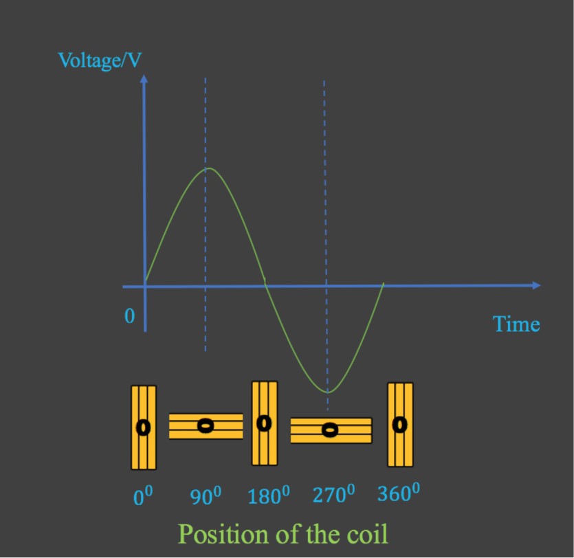
    0-90
    As the coil rotates and moves to its vertical position side AB goes up and side CD goes down. The change in flux is maximum, therefore, the induced current is maximum.

    90-180
    The coil would be in its horizontal position, change in flux is zero, no induced current, so current does not change direction when the loop is parallel to the filed.

    180-270
    The loop is again in its vertical position, where the change in flux is maximum, the current is induced in the opposite direction.

    270- 360
    The loop is back to its horizontal position where there is no change in flux and no induced current.
    Electric Generator and Counter EMF


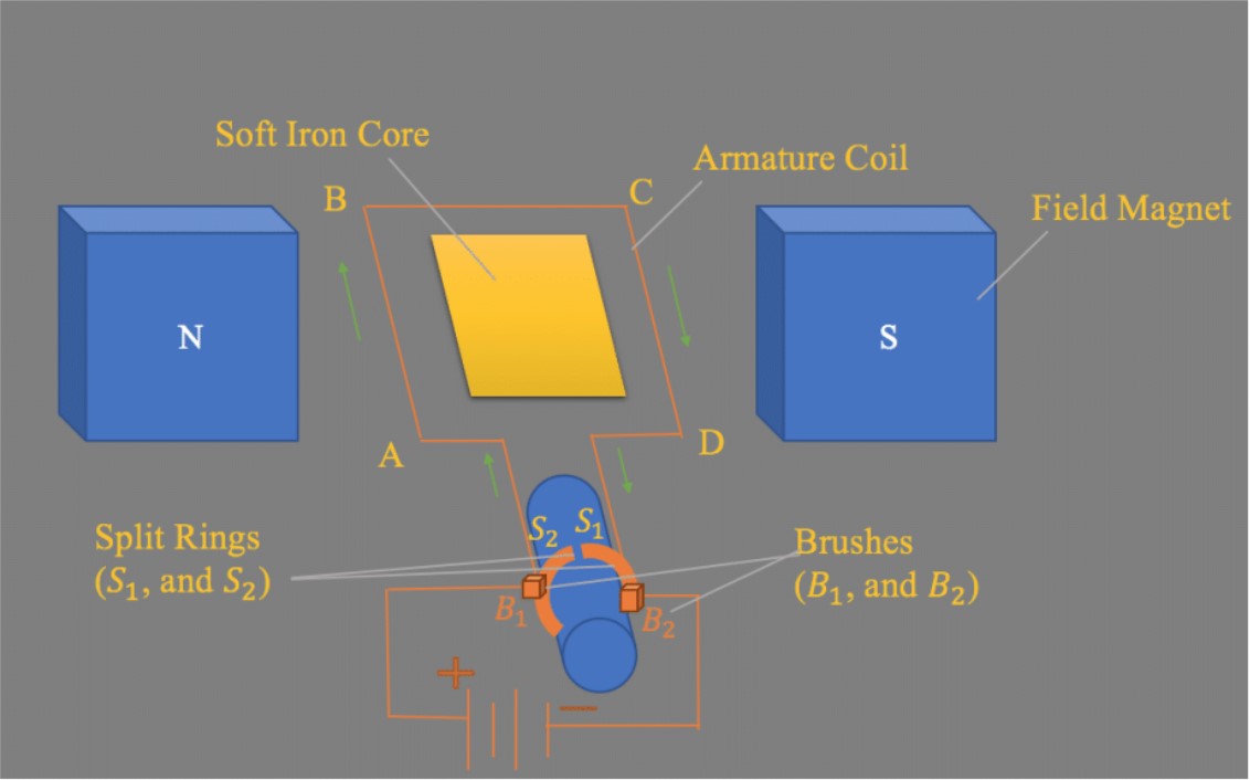
    Dc generator: A generator that consists of many loops of wire wound around an armature that rotates in a magnetic field. The coil is connected to a source of electricity. Since the coil is placed in a magnetic field, as the current flows through the coil, an electromotive force will be produced, thus mechanical energy would be the output of dc generator.

    dc Generator Principles


    0-90
    As the coil rotates and moves to its vertical position side AB goes up and side CD goes down. The change in flux is maximum, therefore, the induced current is maximum.

    90-180
    The coil would be in its horizontal position, change in flux is zero, no induced current, so current does not change direction when the loop is parallel to the filed.

    180-270
    The loop is gain in the vertical position, where the change in flux is maximum, current is induced.

    270- 360
    The loop is back to its horizontal position where there is no change in flux and no induced current.

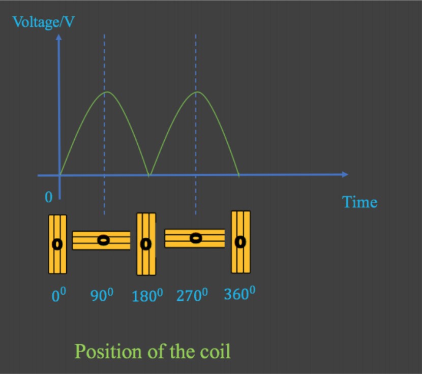
    • The current in the external circuit always flows in one direction.
    • When the loop is in vertical position the brushes are in contact with the rings, maximum current flows through the external circuit.
    • When the loop is in horizontal position, the brushes are not in contact with the rings, no current flows through the external circuit.
    Electric Generator and Counter EMF


    Voltage Vs. Time Graph

    dc generator

    Electric Generator and Counter EMF


    ac Generator

    Electric Generator and Counter EMF


    Counter EMF (Back EMF)

    • Due to the rotation of the coil, the magnetic flux through the coil changes, thus, an induced EMF is produced.
    • According to the Lenz’s law, the induced EMF acts to oppose the motion which is called the Counter EMF or Back EMF.
    • The greater the speed of rotation, the greater the counter EMF.
    • If there is no load, the speed of the motor keeps on increasing till the back EMF will be equal to the input voltage.
    • As the mechanical load increases, the motor rotates at lower speed thus smaller back emf is produced.

    Example
    The armature of a dc motor has a resistance of 8.0 Ω \Omega . The motor is connected to a 110-V power supply, when the motor reaches its maximum speed the back emf is 90-V.

    1. Calculate the current in the motor as it starts up.
    2. Calculate the current when the motor reaches its highest speed.


    1. At the beginning the motor turns very slowly, so there is no back emf.

      I=VR=110V8.0Ω= I = \frac{V} {R} = \frac{110V}{8.0 \, \Omega} = 13.75 AA \simeq 14AA

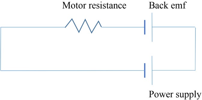
    2. The motor is rotating at its full speed, the back emf is induced and should be included in the circuit,
    Electric Generator and Counter EMF


    VAcross  the  resistor=V_{Across\;the\;resistor} = 110 -90 = 20VV


    I=VR=20V8.0Ω= I = \frac{V} {R} = \frac{20V}{8.0 \, \Omega} = 2.5 AA
    Concept

    Introduction to Electric Generators and Counter EMF

    Welcome to our exploration of electric generators and counter EMF! These fascinating concepts are crucial in understanding how we harness electricity. Electric generators convert mechanical energy into electrical energy, powering our homes and cities. As you'll discover in our introduction video, the process involves a key phenomenon called counter EMF, also known as back EMF. This opposing force plays a vital role in generator operation and efficiency. The video will guide you through the basics, making these complex ideas more accessible. You'll see how magnetic fields and moving conductors interact to create electricity, and how counter EMF affects this process. Understanding these principles is essential for grasping the fundamentals of electrical engineering and power generation. Whether you're a curious student or an aspiring engineer, this introduction will provide a solid foundation for further learning. Let's dive in and unravel the mysteries of electric generators and counter EMF together!

    FAQs

    Here are some frequently asked questions about electric generators and counter EMF:

    1. What is the difference between AC and DC generators?

      AC generators produce alternating current, where the direction of electric flow periodically reverses. They use slip rings to collect current. DC generators produce direct current, which flows in one direction, using a split-ring commutator to convert the alternating current in the armature to direct current in the external circuit.

    2. How does counter EMF affect electric motor performance?

      Counter EMF acts as a self-regulating mechanism in electric motors. As the motor spins faster, the counter EMF increases, limiting the current flowing through the motor. This prevents the motor from drawing excessive current and potentially damaging itself, effectively acting as a built-in speed governor.

    3. What is the relationship between magnetic fields and electric generators?

      Magnetic fields are crucial for electric generators. The principle of electromagnetic induction, where a changing magnetic field induces an electric current in a conductor, is the foundation of generator operation. The strength and configuration of the magnetic field directly affect the generator's output and efficiency.

    4. How can one calculate counter EMF in a DC motor?

      Counter EMF (E) in a DC motor can be calculated using the formula: E = (PΦNZ) / (60A), where P is the number of poles, Φ is the flux per pole in Webers, N is the speed in RPM, Z is the total number of armature conductors, and A is the number of parallel paths (usually 2 for most DC motors).

    5. What are the key components of an AC generator?

      The key components of an AC generator include the stator (stationary part containing wire coils), rotor (rotating part with electromagnet or permanent magnet), slip rings (conductive rings on the rotor shaft), brushes (stationary conductors contacting slip rings), field windings (coils creating the magnetic field), and armature windings (where AC is induced).

    Prerequisites

    Understanding the fundamental concepts that lay the groundwork for more advanced topics is crucial in physics, especially when delving into complex subjects like electric generators and counter EMF (Back EMF). Two key prerequisite topics that are essential for grasping this subject are electric currents produce magnetic fields and induced EMF and Lenz's law.

    The relationship between magnetic fields and electric currents forms the foundation of how electric generators function. When we understand that moving electric charges create magnetic fields, we can better comprehend the principles behind generator operation. This knowledge is crucial because generators essentially convert mechanical energy into electrical energy by exploiting the interaction between magnetic fields and moving conductors.

    Building upon this, the concept of induced EMF and Lenz's law becomes pivotal in explaining the phenomenon of counter EMF. Lenz's law states that an induced current will flow in a direction that opposes the change that caused it. This principle is directly applicable to electric generators, where the induced current creates a magnetic field that opposes the motion of the generator, resulting in the counter EMF effect.

    The interplay between these prerequisite topics and electric generators is fascinating. As the generator's rotor spins within a magnetic field, it induces an EMF in the coils. This process is governed by the principles of electromagnetic induction, which we learn about in the study of Lenz's law and induced current. The induced EMF then drives a current through the circuit, which, in turn, produces its own magnetic field according to the principles of electric currents produce magnetic fields.

    Counter EMF, or Back EMF, is a direct consequence of these interactions. As the generator produces electricity, the induced current creates a magnetic field that opposes the original field, effectively trying to slow down the rotor. This opposition is what we call counter EMF, and it's a perfect example of Lenz's law in action. Understanding this concept is crucial for engineers and physicists working with electric motors and generators, as it affects efficiency and power output.

    By mastering these prerequisite topics, students can develop a robust foundation for understanding more complex electromechanical systems. The knowledge of how magnetic fields and electric currents interact, combined with the principles of induced EMF and Lenz's law, provides the necessary tools to analyze and design efficient electric generators while accounting for the effects of counter EMF. This comprehensive understanding is not only academically rewarding but also practically valuable in various fields of engineering and technology.